Wednesday, December 7, 2016

Getting started with Electric Imp and RGB LED Tail


Electric Imp is again a cool DIY WiFi enabled development platform.It is look like SD card! But it is not an SD card. This one is a cortex M3 processor core.All stuff related to Electric imp is highly innovative.When i got this card for the first time, i was really excited wow what a cool memory card.But when i read about this i understood that this is not even an SD card.We have already discussed couple of WiFi development boards here like esp8266 and particle photon.
    Unlike others there are some cool things in configuring Electric Imp.WiFi configuration is transferred from smartphone to card ,that's too optically!!!!. Yeah!The WiFi credentials are transferred to electric imp card using electric imp app . All the coding is in web IDE we have to write a device code and agent code for a web based app development using electric imp.coding is done in electric imp ide .Imp is housed during working in impee april or other breakout hookup boards,This is a memory card shield like device.Coding in Imp is in language “squirrel”which is similar to C.
Imp with Neopixel
There are many ready-to-connect shield are available for Electric imp.RGB LED tail and env sensor tail are examples.This tutorial explains a simple demo project with RGB LED tail for that you need to create an account in   electric imp. You should sign in in electric imp mobile app and set wifi credentials.then we can create model in IDE.we will have to create two code
1.device code
2.agent code

DEVICE CODE

AGENT CODE
https://docs.google.com/document/d/1mDZ4GKPGtX93AgdYYvMEhvqWfSVQ3g2m8mc-QNAdKGA/edit?usp=sharing


Now flash the above device code to your imp.After flashing you can see the device is online, agent will be online also.Now you will get agent link on that you can change the light effects in neopixel
For example consider this agent link https://agent.electricimp.com/BbM3A-Q4XQcJ?glow

You can change the effect”glow” to “looper” by changing the URL as https://agent.electricimp.com/BbM3A-Q4XQcJ?looper

Here i made a simple DIY decoration lamp using this thing. 


hackster project is given below


Tuesday, October 25, 2016

Particle Photon MQTT Integration With Adafruit.io,IFTTT,and Google drive

For the past few days i have been actively exploring the features of Particle Photon in other IoT platforms.We already have discussed about particle in older posts.In this post i am going to explain
  1. how to visualize sensor data from particle in Adafruit dashboard.
  2. how to create IFTTT channel in between adafruit channel and google drive.
We already discussed that how to visualize data from particle in Thingspeak.In that example we were using data from particle event(particle.publish).But here we are not using particle.publish.Instead we are going to use MQTT protocol.There is library available for mqtt implementation to adafruit.io.

Before starting this you have to
  1. create account in adafruit.io
  2. create account in IFTTT
In the time of creating account we have to note two things
  1. username
  2. AIO key
we have to give these data in particle code

// This #include statement was automatically added by the Particle IDE.
#include "Adafruit_MQTT/Adafruit_MQTT.h"

#include "Adafruit_MQTT/Adafruit_MQTT_SPARK.h"
#include "Adafruit_MQTT/Adafruit_MQTT.h"

/************************* Adafruit.io Setup *********************************/

#define AIO_SERVER      "io.adafruit.com"
#define AIO_SERVERPORT  1883                   // use 8883 for SSL
#define AIO_USERNAME    "username"//replace with your user name
#define AIO_KEY         "8c6b48de9fab4r2da9f2463e79373ee"//replace with your key

/************ Global State (you don't need to change this!) ******************/
TCPClient TheClient;

// Setup the MQTT client class by passing in the WiFi client and MQTT server and login details.
Adafruit_MQTT_SPARK mqtt(&TheClient,AIO_SERVER,AIO_SERVERPORT,AIO_USERNAME,AIO_KEY);

/****************************** Feeds ***************************************/

// Setup a feed called 'voltage' for publishing.
// Notice MQTT paths for AIO follow the form: /feeds/
Adafruit_MQTT_Publish voltage = Adafruit_MQTT_Publish(&mqtt, AIO_USERNAME "/feeds/voltage");


/*************************** Sketch Code ************************************/
int x = 0;
void setup()
{
    Serial.begin(115200);
    delay(10);
    pinMode(A0,INPUT);
    Serial.println(F("Adafruit MQTT demo"));
   
    // Setup MQTT subscription for onoff feed.
    mqtt.subscribe(&onoffbutton);
}

void loop()
{
    int value=analogRead(A0);
  if( mqtt.Update() ){
 
        voltage.publish(value);
     
  }
    delay(10000);//delay is important here
}


please not the lines in code

#define AIO_USERNAME    "username"/
#define AIO_KEY         "8c6b48de9fab4r2da9f2463e79373ee"
replace those lines with your username and AIO key

Here I am just posting some data from analog pin A0 to adafruit.io using MQTT.

Circuit

wire up the circuit as given above and upload the above code after adding the library.
Now open adafruit.io
In Your Feeds tab you can see our new feed "voltage"by clicking on that you can see simple graphical visualization of the feed like below
Now we can create our own dashboard by clicking Your dashboard tab. We can add different blocks to our dashboard and add our feed to it

You can set labels for graphs,can set maximum value and many other features.You can test your own blocks.After setting dashboard rotate the preset and change voltage in A0 pin.Now you can see values changing in dashboard according to  changes in hardware

IFTTT recipes integration

No we can integrate this with IFTTT for that click on settings tab
 Add IFTTT in settings page and save.
Then we can set up our own recipe with adafruit and google drive channels.You can see all available channels in channels tab
if you are not already connected with adafruit channel, connect  with it here
then connect with google drive channel
Now by clicking create new we can make our own recipe


You can also use my published recipe for testing

IFTTT Recipe: adafruit dashboard google drive integration connects adafruit to google-drive


Now you open your google drive you can see one new folder created in the  path adafruit/io/{{FeedName}}
you will have new spreadsheet created named adafruit.io.{{FeedName}}
Now open that google sheet you can see data  from adafruit dashnoard.


Here in this recipe we are posting to spreadsheet if the feed value is greater than 700.I think there is much more platforms are available for this king of integration.I am still exploring.And I would like to mention one more thing  that you can directly integrate particle with IFTTT.particle have its own channel in IFTTT .It can access particle events and particle variables.I had some hacks using those also,like email triggering according to sensor value,PUSH notification using IF notification channel etc
I will try to post more about these in my next posts.


Thursday, October 20, 2016

Webhook from Particle Photon to Thigspeak

In one of my old blog post we already had a introduction about the Particle IoT platform.As we discussed there particle events have many application and can be integrated to many other IoT services like webhooks,Thingspeak,IFTTT,Ubidots, etc.In this post i am going to share that how to create a webhook to thingspeak from particle.
It is very simple ,actually we are just using the particle event (particle.publish) here.No tactical coding is needed to send data to thingspeak from particle using webhook.for demo purpose i am just showing how to visualize varying analog voltage graphically in thingspeak.Here i am using a potentiometer to change the analog voltage.You can change it to any other sensor and visualize data graphically.even you can embed this graph into your personal site.

Wire up your particle photon as shown in the above circuit.Then open particle Web IDE and upload the below code to your photon.The code is simple it is just publish an event which is publishing the analog voltage on pin A0 in every 1 minute.

void setup(){
pinMode(A0,INPUT);
}
void loop() {
// Get some data


int value=analogRead(A0);
String val=String(value);


// Trigger the webhook
Particle.publish("value", val, PRIVATE);
// Wait 60 seconds
delay(60000);
}


Now we have published an event named "value". We can see the updates of this event in particle console.
Now we can create new  integration .For that select new integration in console and select webhook
You can see the above screen.Now we have to create a channel in thingspeak and fill the data to above form.Now open thingspeak and create a new account if you are new to thingspeak .Then create a new channel and note the channel API


Now we can fill the webhook form in particle console.Fill the boxes like below
  • Event Name=value
  • URL=https://api.thingspeak.com/update
  • Request type = POST
  • Device = Your device name
Now press advance setting tab and fill the boxes  

  • api_key: YOUR_API_KEY
  • field1: {{PARTICLE_EVENT_VALUE}}

now the webhook to thingspeak is created.Now you can see graphical representation of your sensor values in thingspeak


You can also embed the graph in your site also.

Tuesday, October 11, 2016

Arduino Wireless Remote with 2.5GHz NRF24L01


In many projects we may need wireless communication between different microcontrollers.For that we are using different modules like XBee/Zigbee, simple RF,bluetooth/BLE etc.Now on this blog I am going to explain a different wireless transceiver module NRF24L01 which is working on 2.5GHz ISM band frequency.

I was so lazy to work on this module since this is not a breadboard friendly module and i was not having female to male headers.And I was too lazy to make a connection circuit to this module to breadboard.Meanwhile i got an invitation from collaborizm a platform for entrepreneurs/engineers/creatives.I was about to have a look on a project on NRF24L01.So I tested my module for the first time.

NRF24L01 is designed for ultra low power wireless applications.It is a transceiver with an embedded base band protocol engine named Enhanced ShockBurst™.The module can be interfaced with arduino or any other microcontrollers via SPI bus.

Applications
  1. In wireless PC peripherals like keyboard,Mouse etc
  2. Remotes
  3. Toys
  4. Home automation
  5. Asset tracking systems
  6. Active RFID systems
  7. Ultra low power sensor networks
Demo project 
Here I am going to showcase a simple NRF24L01 based transmitter and receiver.Transmitter is act as remote control and receiver will ON/OFF a  LED in accordance with the data received.I am using arduino pro minis as my microcontrollers you can use your own arduinos.
you can  find the  arduino library for nrf24l01 here

Connection 

nrf24L01------Arduino
  • vcc-----3.3V
  •  GND----GND
  • MISO---pin12
  • MOSI---pin11
  • SCN---pin10
  • SCK---PIN13
  • CE----pin9
The connection is same for both transmitter and receiver you can find the fritzing project  files here


Transmitter


Receiver


Saturday, September 10, 2016

Control Your Arduino BLE Device Using Smartphone

Bluetooth is one of the main connectivity technique used for short range connectivity in many devices.After the evolution of Bluetooth low Energy  it becomes more attractive to engineers and DIY hackers because of its low energy consumption.Many modules are available in the market which are easily interfaceable with  ‘Hackers toys’ like arduino,particle,raspberry pi,etc.Because of this high demand Arduino release their Arduino 101/Genuino 101 with inbuilt BLE module and raspberry pi3 has also got the inbuilt BLE.


This is the era of smartphones.People's daily life is highly depends on their smartphones.Almost all wearables are communicating with smartphones Via Bluetooth.There are many application of BLE in healthcare devices also which senses body sensor values like heartbeat and transmit into smartphones and then to cloud.
I have worked on classic bluetooth module HC05 as well as Adafruit Bluefruit  BLE  module.Many BLE modules are available in the market.In my research most of these BLE modules are working in peripheral mode.In this mode modules only can advertise their payload.It can not scan any other BLE modules in range.For scaning you will have to use BLE modules which supports Central mode.Usually the BLE modules in laptops and  smartphones are coming with central mode.there are some DIY friendly central mode supported bluetooth modules also available in the market.None of them are tested by me.HM10 ,BLE mini RedBear and BLE nano RedBear are such modules which can be used in central mode

Adafruit Bluefruit LE UART Friend is One of the coolest and easily interfaceable BLE modules available in the market.Since it is developed by Adafruit there are many documentation and tutorials are available in the internet.Adafruit also giving an arduino support library

The examples are  written to communicate with adafruits bluefruit LE app.There are codes available for BLE as beacons,uribeacons,eddystones,etc.Now i would like to explain how to modify this codes to our way.Ie how to control things using your samrtphone and BLE.

 Example for  arduino BLE to android communication


You can find the fritzing file here
You can find the hackster project here
  List of components
  1. Arduino Pro Mini
  2. Adafruit Bluefruit LE UART Friend 
  3. Buzzer
  4. LED
  5. Resistor 330 ohm
  6.  bluefruit LE app or any other custom designed android app
Connection
Arduino pin 9 ----Bluefruit RX
Arduino pin 10---Bluefruit TX 
Arduino pin 11---Bluefruit CTS
Arduino pin 12---Bluefruit Mode pin
Arduino GND---Bluefruit GND
Arduino Vcc---Bluefruit Vcc
Arduino pin 3---led
Arduino pin 6---Buzzer


 This example demonstrates how a device can be controlled using your smartphone.Here  i am  controlling An LED and buzzer using android App.This device will read incoming data from any other BLE device(which is working in central mode)and do actions.

    Incoming data                      Actions
character 1(ASCII49)  ----------  LED ON
character 2(ASCII50)  ---------- LED OFF
character 3(ASCII51)  ---------- will reply "Thank you for reading wiring it my way"
character 4(ASCII52)  ---------- BUZZER ON
character 5(ASCII53)  ---------- BUZZER OFF

You can use your own BLE app.Here I am Using bluefruit LE app from adafruit. in that after pairing  your device to your phone open UART mode in your app and send different characters like 1,2,3,4,5 and test your BLE.

As you know this is only the basic intro off BLE.Now try your own devices like BLE controlled toys,sensor data apps etc.please commend your BLE experiences.


Friday, August 5, 2016

MQTT Publish And subscribe Using RaspberryPi,Esp8266,And Particle Photon


Current trend in DIY is IoT based projects. The present professional  electronics engineering industry is also now focusing to IoT.There are many existing protocols are there for making connection with your device with Web.If we need real time data in every second or less than that,We will need a fast internet connectivity protocol.And it should use very little bandwidth.Here we have MQTT.

MQTT is an extreamly light weight connectivity protocol which is mainly used for machine to machine /IoT applications.It was formerly known as MQ Telemetry Transport.it is a publish/subscribe based messaging protocol for use on the top of TCP/IP protocol.MQTT is very helpful where network bandwidth is limited.Many IoT companies uses MQTT for their applications.


There are several MQTT brokers are available In this example we are using mosquitto broker.In MQTT there is several methods are defined like
1.Connect
2. Disconnect
3.Subscribe
4.Unsubscribe
5.Publish

As DIY hackers we also make use of MQTT in our projects .Many of the boards supporting WiFi is also supports MQTT.Here I am going to discribe MQTT broker in Raspberry Pi.And MOTT Client in Raspberry Pi,Particle Photon,esp8266.


I have no plan to explain the MQTT protocol ,but i would like to explain how it can be implemented  in our DIY project.In MQTT protocol we will have broker and clients.clients are those which can publish and subscribe to some topics created in broker.Broker is responsible for all fitering and all.ie broker will receive all messages and it will send those messages to corresponding subscribed clients.MQTT client libraries are easly available for many devices and in many coding languages.


It is very easy to set up a MQTT broker in linux system.As this blog is mainly explaining DIY projects I would like to Explain how to install MQTT broker in Raspberry Pi,which is one of the best toy of an electronics hobbyists.And I will be sharing how to set up MQTT clients(publish/subscribe) in Raspberry pi, Particle photon,esp8266,which are main tools in IoT hardware prototyping.All these are inspired from community.So I would like to thank all bloggers in community.


First we can Setup a MQTT broker in our Raspberry pi.For installing Mosquitto broker follow the steps below.


How to install MQTT broker in Raspberry pi

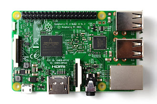
First we have to import repository package for mosquitto into our raspberry pi.For that  open the Raspberry pi terminal and run below commands.I used a Raspberry Pi 3 in jessie with 16GB microSD card 


sudo apt-key add mosquitto-repo.gpg.key
Now we have to make available this repository to apt by using below command


cd /etc/apt/sources.list.d/


Now follow below commands


sudo -i
for updating pi
sudo apt-get update
apt-get update
After updating we can install mosquitto MQTT broker running below command
apt-get install mosquitto


How to install MQTT Client in Raspberry pi

So  now we successfully installed MQTT broker in our Raspberry Pi.Now we can install MQTT client by below command
apt-get install mosquitto-clients
Now the client library for MQTT is installed


So we successfully installed MQTT.Now we can start publishing and subscribing to some topics.


How to use MQTT client as Publisher
To publish a data “wiring_it _my _way ” to  a topic named “color”we can use the below commands


If the broker is installed in the same Raspberry pi
mosquitto_pub -h localhost -t color -m wiring_it_my_way


If the broker is installed in different Raspberry pi
mosquitto_pub -h 192.168.0.114 -t value -m wiring_it_my_way


How to use MQTT client as Subscriber
If the broker is installed in a different system then for subscribing a topic named “color” just run the below command


mosquitto_sub -h 192.168.0.114 -t color             
Here the IP in the command is lP of broker  raspberry pi/system
if the client is running in the same raspberry pi where broker is installed then use the below command for subscribing a topic named “color”
mosquitto_sub -h localhost -t color

ESP8266 as MQTT client

   As we know  ESP8266 WiFi Module is a self contained SOC with integrated TCP/IP protocol stack that can give any micro controller access to our WiFi network.Also we can program the ESP8266 directly from our arduino IDE.There many libraries available for ESP8266 in the community.I am sharing two code snippets .One is for publishing using ESP8266 and the other is for publishing and subscription.


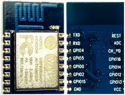
Here our broker is set upped in raspberry pi so we have to note the IP of the raspberry pi and include in our ESP8266 arduino code.
Here given code is only basic code please make your own variety with sensors and actuators have fun.And please share in comments  I used an ESP8266-12


 Particle Photon as MQTT client

In one of my previous post we have discussed about the particle module,which is one of the best choice for IoT based prototyping.Particle web IDE contains MQTT libraries in it.By including those libraries we can easly subscribe or publish to a MQTT topic.Here also we have to give IP address of our pi in Particle code.
.

// This #include statement was automatically added by the Particle IDE.
#include "MQTT/MQTT.h"

// This #include statement was automatically added by the Particle IDE.
#include "MQTT/MQTT.h"

#include "MQTT/MQTT.h"
String sensor;
byte server[] = { 192,168,0,115 };//the IP of broker
void callback(char* topic, byte* payload, unsigned int length);
MQTT client(server, 1883, callback);

void callback(char* topic, byte* payload, unsigned int length) {
    char p[length + 1];
    memcpy(p, payload, length);
    p[length] = NULL;
    String message(p);

    if (message.equals("RED"))   
        RGB.color(255, 0, 0);
       
    else if (message.equals("GREEN"))   
        RGB.color(0, 255, 0);
    else if (message.equals("BLUE"))   
        RGB.color(0, 0, 255);
    else if (message.equals("wiring_it_my_way"))   
        {RGB.color(255, 0, 0);
        delay(1000);
        RGB.color(0, 255, 0);
        delay(1000);
        RGB.color(0, 0, 255);  
        delay(1000);}
    else   
        RGB.color(255, 255, 255);
    delay(1000);
}

void setup() {
    pinMode(A0,INPUT);
    RGB.control(true);
    client.connect(System.deviceID());
    if (client.isConnected()) {
        client.subscribe("color");//color is the topic that photon is subscribed
        client.publish("fun", "hello");//publishing a data "hello" to the topic "fun"
       
    }
}

void loop() {
    int sensor_value =analogRead(A0);
    sensor =String (sensor_value);
    if (client.isConnected())
        client.loop();
         client.publish("value", sensor);//publishing a sensor data  to the topic "value"


}   


when i heard the name MQTT for the first time i thought it will be very difficult for a hardware geek like me.But the broker set up was very easy and straight forward.It makes MQTT very easy.Regarding quality there are methods in MQTT to retain messages,confirmation etc.I don't have a plan to explain those in this post.Now make your own project in MQTT in whichever platform you like and please let me know your ideas in comments.  


 you can find the hackster project here